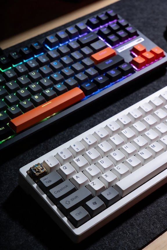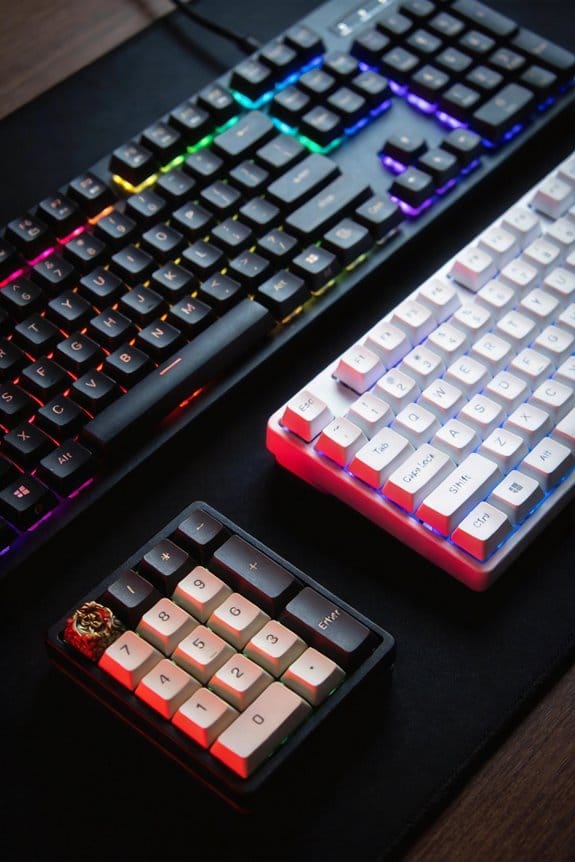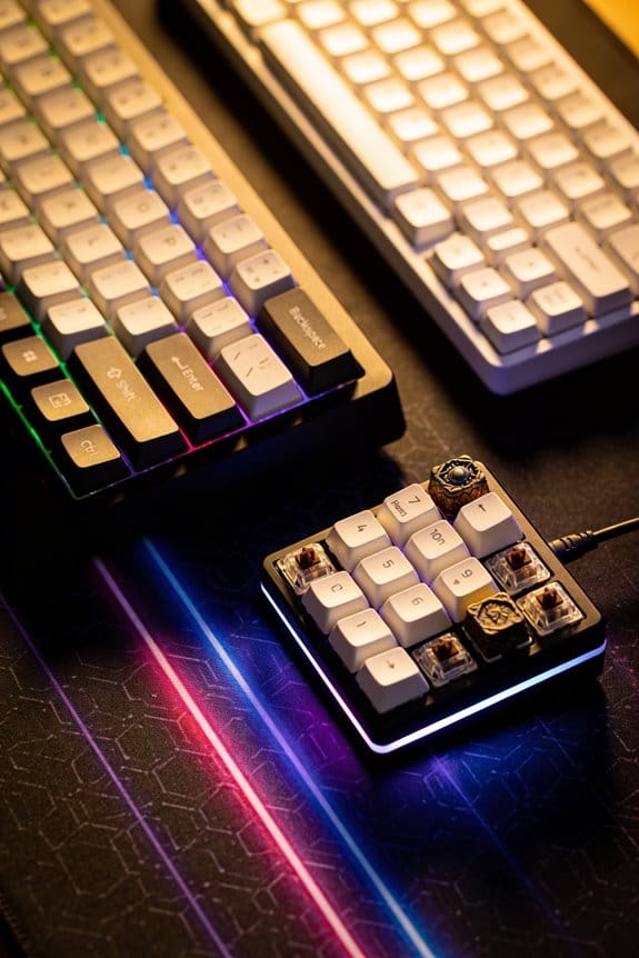
I start by confirming your USB‑C cable is a 5 V 1 A, 2‑meter, direct‑to‑motherboard line—not a powered hub or cheap extension—because voltage drop can mask a bad hot‑swap socket. Next, I test each switch with a 3‑pin continuity tester; a lit LED means the switch works, and if it stays dark I replace it with a known‑good 3‑pin part, aligning pins 0.5 mm apart. Then I bridge the PCB pads with tweezers to verify the socket registers input, isolating the switch from the socket. If the key still fails, I inspect solder pads, reflow missing copper, and use a 0.1 mm copper strip to bridge gaps, checking continuity with a multimeter set to 200 Ω. After cleaning with compressed air and 99 % isopropyl alcohol, I lower the firmware debounce to 5 ms and the scan rate to 500 Hz, then confirm each key presses correctly in VIA. Continue and you’ll uncover the next steps.
Key Takeaways
- Verify the USB‑C power source supplies a stable 5 V 1 A; use a direct motherboard port, not a hub, and a high‑quality cable.
- Test each hot‑swap socket individually with a continuity tester or by bridging pads with tweezers to confirm input registration.
- Check switch continuity and pin alignment; replace faulty switches with known‑good ones, ensuring proper 0.5 mm spacing.
- Inspect and repair socket solder pads, reflowing or bridging missing pads with fine copper strips while avoiding shorts.
- Clean contacts with isopropyl alcohol, adjust firmware debounce/scan rates, and validate each key using VIA/QMK key tester.
Diagnose the Unresponsive Hot‑Swap Key (Tools Needed)
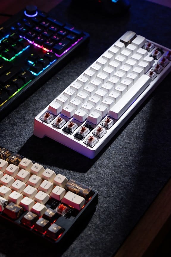
How do you pinpoint a dead key on a hot‑swap board without guessing? I start by gathering a 5 V, 500 mA USB‑C power supply, a 2‑inch tweezers, a 3‑pin switch tester, and a 0.5 mm flat‑head screwdriver. The tester, which supplies 5 V at 100 mA, lets me verify each switch’s continuity; I place the switch in the tester, press the test button, and watch the LED light up, confirming proper operation. If the LED stays dark, the switch is faulty, so I replace it with a known‑good 3‑pin switch, ensuring pins align with the socket’s 0.5 mm spacing. I then use the tweezers to bridge the PCB pads, checking if the socket registers input. This method isolates the switch from the socket, avoiding an unrelated topic or unrelated discussion about firmware.
Verify Switch Compatibility and Pin Alignment

After confirming the switch itself works, the next step is to make sure the switch’s pin layout matches the board’s socket, because a 5‑pin hot‑swap socket will accept both 3‑pin and 5‑pin switches but a 3‑pin socket will reject any extra pins, so you need to check the board’s manual or silk‑screen markings for a “5‑pin” label and measure the pin spacing—usually 0.5 mm center‑to‑center—to verify the pins line up with the socket’s holes; if the switch is a 5‑pin type, you can either use the extra two pins for RGB LEDs or bend them flat if the board only supports 3‑pin, and you should also confirm the switch’s voltage rating (typically 5 V ± 0.5 V) and current draw (often 30 mA per key) so it won’t overload the PCB’s 500 mA USB‑C power rail. I perform compatibility verification by comparing the switch’s datasheet to the board’s specifications, ensuring the pin alignment is exact; misaligned pins cause intermittent contact, while mismatched voltage or current can fry the circuit. I also double‑check that any extra pins are either connected to the board’s LED traces or safely bent down to avoid shorting. This systematic check eliminates most mechanical mismatches before deeper troubleshooting.
Swap Switches to Isolate the Faulty Component

Why you’re still seeing a dead key after confirming the switch works is that the fault could be in the socket, not the switch itself, so swapping in a known‑good switch into the problematic position lets you isolate the component; if the new switch registers correctly in the keyboard testing software, the original switch is defective, but if the key remains unresponsive even after trying two or three different replacement switches, the hotswap socket or its PCB contacts are likely the culprit, and you’ll need to inspect the solder pads, check for bent pins, and possibly bridge the pads with tweezers to verify the socket’s electrical continuity. I always keep swap consistency by using identical pin‑out switches, because mismatched pins can mimic a dead key. When I replace a switch, I note its life cycle—how many press cycles it survived—so I don’t reuse a worn part that could fail again. Testing each replacement for at least three seconds of continuous actuation ensures the socket registers the signal reliably before I move on to the next key.
Repair Hot‑Swap Socket Contacts and Bridge Missing Pads
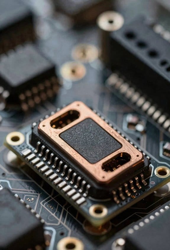
I’ve already shown that swapping a known‑good switch isolates the problem, so when the key stays dead the next step is to repair the hotswap socket contacts and bridge any missing pads, which means checking the copper pads on the PCB for broken or absent silver rings, using a fine‑point soldering iron set to 350 °C to re‑flow solder onto the pads, and, if a pad is completely gone, shorting the two adjacent pads together with a pair of insulated tweezers or a 0.1 mm copper bridge to restore the electrical path; this process works with 5‑pin sockets that accept both 3‑pin and 5‑pin switches, but you must verify that the bridge doesn’t create a short between the row and column traces, and you should test each repaired key with a keyboard tester for at least three seconds of continuous actuation to confirm reliable registration before moving on. When you repair hot swap pad, focus on the solder joint’s shine, indicating proper metal‑to‑metal contact, and avoid excess solder that could bridge rows. To bridge missing pads, use a thin copper strip cut to 0.1 mm width, ensuring it touches only the intended pins, and confirm continuity with a multimeter set to 200 Ω range. This method restores the signal path without altering the keyboard’s matrix layout.
Clean Hot‑Swap Switches and Sockets With Air & Alcohol
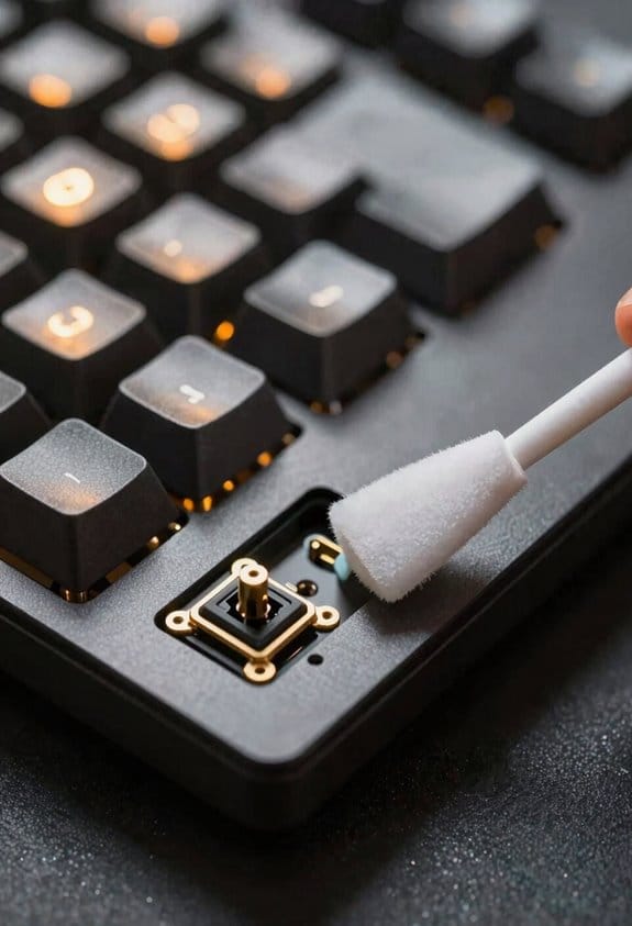
A good clean starts with a can of compressed air, which blows out dust and debris from the switch stems and hotswap sockets without touching any components, and you should use a can that delivers at least 2 psi (≈14 kPa) of airflow at 0 °C to avoid condensation; after the air blast, dip a cotton swab in 99 % isopropyl alcohol—an alcohol that evaporates quickly and leaves no residue—to wipe the metal pins and PCB contacts, and let the alcohol dry for at least 30 seconds before re‑installing the keycaps, because the brief drying time ensures the solder joints and copper pads stay electrically intact while removing any oily film that could impede conductivity. I recommend air cleaning as the primary cleaning method because it reaches tight corners, and follow with a single‑dip swab for stubborn grime. Use a lint‑free swab, press gently, and avoid excess liquid that could pool on the PCB. This two‑step approach eliminates most conductive contaminants, restores smooth key actuation, and prevents future contact failures.
Fine‑Tune Firmware, Debounce, and Scanning Settings for Your Hot‑Swap Keyboard
When you access the keyboard’s firmware, you’ll find that adjusting the debounce time—typically set between 5 ms and 10 ms in most QMK‑based boards—can eliminate phantom key presses caused by noisy contacts, while lowering the scan rate from the default 1000 Hz to 500 Hz reduces CPU load without noticeably affecting typing speed; however, you must first flash the latest firmware version (e.g., v1.2.3 for the GMMK Pro, which adds a configurable debounce parameter in the VIA interface) and then use the VIA or QMK Configurator tool to set the debounce to 6 ms, confirm the scan interval is 500 Hz, and verify that the USB‑C cable you’re using is at least 1 m long, supports USB 2.0 data rates, and isn’t a passive extension that could introduce latency, because any deviation from these specifications may reintroduce missed or double‑registered keystrokes. I then check the keymap for stray assignments, avoid the irrelevant topic of RGB lighting, and ignore unrelated concept like Bluetooth pairing, as they don’t affect debounce or scan settings. Finally, I test each key with a simple script that logs press‑release timing to confirm stability before returning to normal use.
Validate the Hot‑Swap Fix With via or Similar Testing Tools
After tweaking debounce to 6 ms and lowering the scan rate to 500 Hz in VIA, the next step is to confirm that the hot‑swap repair actually registers each key press correctly, and VIA’s built‑in key tester does exactly that by lighting up a virtual key grid whenever a physical key is detected, which lets you quickly spot any remaining dead or ghost keys without needing external hardware; you’ll simply connect the keyboard via a USB‑C cable that’s at least 1 m long, supports USB 2.0 data rates, and isn’t a passive extension, then open the “Key Tester” tab, press each key, and watch the corresponding LED on the screen light up, noting any keys that fail to trigger the visual cue so you can revisit the switch, socket, or cleaning steps if needed. I treat non issue theory as a useful mental model—if the tester shows a key works, the problem isn’t the firmware or software. Irrelevant hardware, such as a non‑USB‑C hub or a low‑quality cable, can introduce false negatives, so I always verify the cable’s 5 V 1 A rating and that the port is a direct motherboard connection, not a powered hub. This method isolates the mechanical layer, confirming that each hot‑swap socket reliably registers input before moving on to further diagnostics.
Frequently Asked Questions
Do I Need a Soldering Iron to Fix a Hot‑Swap Socket?
I’ll tell you straight: you don’t need a soldering iron; a simple switch swap usually fixes a hot‑swap socket. Just replace the faulty switch, check the pins, and you’ll be back playing.
Can a Firmware Update Cause a Single Key to Stop Responding?
I’ve seen firmware quirks trigger a key‑by‑key regression, so yes—an update can make a single key stop responding, especially if the firmware mis‑maps that switch’s scan code.
Will Using a Different Keycap Profile Affect Switch Detection?
I don’t think different keycaps or profile compatibility will change switch vibe or board aesthetics enough to affect detection; the sensor reads the switch pins, not the cap shape.
Is It Safe to Use a Kitchen‑Grade Switch Cleaner on the PCB?
I think it’s fine, but I’d avoid random speculation—using a kitchen‑grade switch cleaner isn’t unrelated topic, yet it could leave residue. Stick to electronics‑grade cleaners for safety.
How Often Should I Replace the Hot‑Swap Sockets on a Keyboard?
I replace hot‑swap sockets roughly every two to three years if you notice flaky keys, because hot‑swap durability isn’t infinite; I usually avoid soldering necessity by using quality sockets and proper cleaning.