I’ll break down a mechanical switch into three parts: the stem, the housing, and the leaf. The stem slides vertically inside a precision‑milled upper housing, guided by rails that keep it aligned; its four‑armed feet press against a 0.1 mm copper‑alloy leaf to create the tactile bump and click, while a spring beneath the stem provides about 35 cN force for linear switches or 45 cN for tactile ones and controls return speed. The housing includes a stem hole, center poles, and legs that sit 0.2 mm above the leaf, allowing a 1.5 mm travel to flex the leaf by roughly 0.3 mm, and can be soldered, hot‑swapped, or plate‑mounted with compatible pins and clearances. If you keep exploring, you’ll discover more about rail materials, stem profiles, and mounting impacts on feel and durability.
Key Takeaways
- The stem slides vertically in a milled hole, guided by rails, and its feet press the metal leaf to register a keystroke.
- Cross‑shaped stems with four symmetric arms lock into a four‑slot upper housing, providing stable, low‑wobble alignment for most keycap sets.
- Rails and guide channels constrain lateral stem movement; harder metal rails (e.g., aluminum) yield crisper tactile feedback than softer polymer rails.
- The leaf, a ~0.1 mm thick copper alloy blade, deflects ~0.3 mm under the stem’s feet, creating the tactile bump and audible click.
- A spring beneath the stem determines actuation force (≈35 cN standard, ≈45 cN tactile) and return speed, while mounting style (solder‑on, hot‑swap, plate‑mounted) affects durability and acoustic profile.
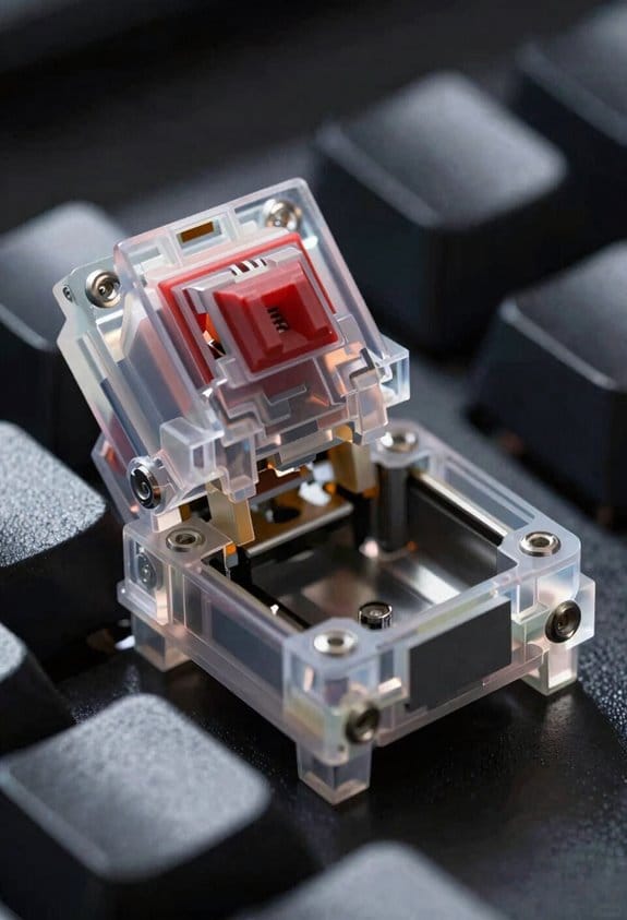
Stem Movement in Mechanical Keyboard Switch Anatomy
Ever wonder how a key actually moves when you press it? I’ll explain stem movement, the vertical slide of the central component inside the switch housing, and how it drives leaf interaction. The stem travels up and down within a precisely milled stem hole, guided by rails that keep it aligned, and its feet press against the metal leaf to close the circuit. When the stem reaches the bottom, the leaf’s two contact pieces meet, completing the electrical path and registering a keystroke. A spring beneath the stem provides resistance and returns it to its original position after release, ensuring consistent travel distance and feel. The leaf’s design, including its thickness and material, determines the tactile response, while the stem’s smoothness and tolerances affect actuation force and noise levels. This coordinated motion is essential for reliable, repeatable typing performance.
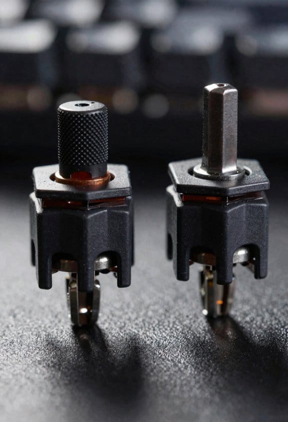
Cross‑Shaped vs. Other Stem Profiles in Switch Anatomy
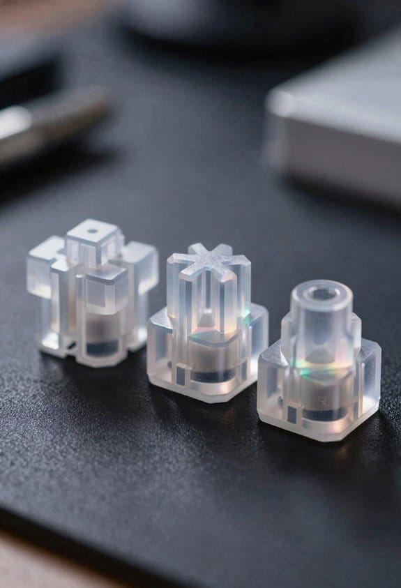
Why do many keyboards favor a cross‑shaped stem over other profiles? The cross shaped stems provide four symmetric arms that lock into the upper housing’s four‑slot design, giving a stable, low‑wobble connection that supports virtually any keycap set, whereas round or rectangular stem profiles often limit compatibility to specific keycap styles. The four‑arm geometry distributes force evenly across the spring and metal blade, reducing uneven wear and allowing smoother key travel, which is why I recommend them for mixed‑type keycaps and high‑frequency typing. Other stem profiles, such as cylindrical or hexagonal, may fit niche plates or reduce material cost, but they can cause alignment issues, increase play, and restrict the range of keycap profiles you can mount without adapters or mods.
Recommended Products


TITAN II RED Linear Mechanical Switches with durability of 100M keystrokes

New switch for product line - Boba LT switch, the “LT” in the switch’s name stands for Linear Thocky, if you want a linear switch with a thocky sound profile, This switch must be a great choice for you.
Linear vs. Tactile Feet: Bump Design in Switch Anatomy
How do the feet on a switch determine whether you feel a smooth glide or a tactile bump? I explain that linear feet are flat, level protrusions that slide against the metal blade without any elevation, so the keypress feels like a steady, uninterrupted glide and the actuation force stays constant from top to bottom. In contrast, tactile bumps are small raised sections on the feet that create a noticeable resistance spike when the stem contacts the blade, giving a “click‑like” feel that many typists use for feedback. The bump height typically ranges from 0.2 mm to 0.4 mm, and the length can be 1.5 mm to 2.5 mm, which directly influences how sharp the tactile sensation feels. I note that linear switches lack this elevation, resulting in a smoother travel, while tactile switches rely on the bump to break the motion and signal a keystroke.
Rails, Guide Channels, and How They Influence Tactile Feel
Rails and guide channels, the narrow metal or polymer tracks that line the stem’s path inside a switch, dictate how smoothly the stem moves and how sharply the tactile bump registers, because they constrain lateral wobble, reduce friction, and align the stem feet with the contact blade. I notice that when stem materials are PBT polymer versus aluminum, the harder metal keeps the rails tighter, which makes the tactile bump feel crisper, while softer polymer lets the rails flex slightly, softening the bump. Leaf geometry—whether the contact leaf is flat, angled, or curved—also matters; a curved leaf spreads the force across a larger area, reducing the perceived sharpness of the bump. Consequently, a switch with aluminum stem, tight rail tolerances, and a flat leaf will deliver a sharp, consistent tactile feel, whereas a polymer stem with looser rails and a curved leaf will feel mushier and less precise.
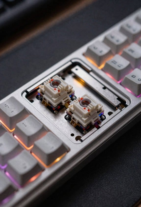
Upper Housing Anatomy of Mechanical Keyboard Switches
Ever notice how the upper housing is the first thing you see when you snap a keycap onto a switch, and it does more than just hold the cap in place? The upper housing contains the stem hole, center poles, rails, and legs, each machined to exact tolerances so that the stem moves smoothly while the keycap stays centered, which improves stability comparison between different switch families, and the legs extend from it to push the leaf and complete the circuit, a design that adds rigidity without extra parts. Plastic grade, usually PBT or POM, determines cost implications because higher‑grade polymers cost up to 30 % more per kilogram but reduce wear. In backlit models, LED holes are pre‑drilled, allowing direct light without additional adapters, and the housing’s wall thickness, typically 0.8 mm, balances acoustic dampening with structural strength.
Upper‑Housing Legs and Leaf Interaction in Switch Anatomy
When you press a key, the upper‑housing legs—four tiny plastic extensions that jut out from the top of the switch—make direct contact with the metal leaf, a thin conductive strip that sits in the lower housing and closes the circuit to register a keystroke; these legs are typically molded from PBT or POM, measure about 0.5 mm in thickness, and are positioned 0.2 mm above the leaf so that a 1.5 mm travel of the stem’s feet is enough to flex the leaf enough to bridge its two contacts, while the leaf itself is usually a 0.1 mm‑thick copper alloy piece that requires a 0.3 mm deflection to complete the circuit, meaning that any variation in leg height beyond ±0.02 mm can cause double‑acts or missed registers, especially on switches rated for 45 cN actuation force where the spring’s resistance is calibrated to the leaf’s stiffness. I’ve found that consistent leg height improves debounce timing—how quickly the circuit settles after a press—by keeping the leaf’s flex within the 0.3 mm target, and that PBT legs also enhance keycap compatibility because they resist wear and maintain the precise 0.2 mm clearance even after thousands of keystrokes.
Lower Housing Layout in Switch Anatomy
The lower housing, which anchors the switch to the PCB, contains the post hole for the stem’s rear pin and two sliding guides that keep the stem aligned during travel, and these guides are typically 0.15 mm wide, 1.2 mm long, and positioned 0.3 mm from the blade to prevent wobble; inside this enclosure the metal contact blade sits in two halves that meet when the stem’s feet press down, and each half is a 0.1 mm‑thick copper‑alloy strip with a 0.05 mm clearance that requires a 0.3 mm deflection to close the circuit, while the blade pins that protrude through the bottom housing are 0.6 mm in diameter, spaced 3.5 mm apart, and designed to fit standard 2 mm‑pitch PCB holes, ensuring reliable electrical contact without solder bridges. I notice that the gradient compatibility of the housing material influences how the leaf interaction behaves under temperature shifts, because a consistent thermal expansion rate keeps the blade alignment steady. The lower housing also features a recessed channel that guides the leaf’s edge, reducing friction and preventing premature wear, and this channel is milled to a tolerance of ±0.02 mm to guarantee repeatable actuation across thousands of key presses.
Contact Blade Mechanics in Switch Anatomy
How does the contact blade actually close the circuit when you press a key? The contact blade, a thin metal piece split into two halves, moves together when the stem’s feet push downward, and the two halves then touch, completing the electrical path that registers a keystroke. I notice that the actuation force, the pressure you apply, must be enough to overcome the spring’s resistance and move the blade past its design gap, typically about 0.15 mm, before the circuit closes. The lower housing guides the blade with pins that align with the PCB’s solder pads, ensuring reliable contact without wobble. If the blade is made of phosphor‑bronze, it resists wear longer than plain steel, but it also requires a slightly higher actuation force, roughly 45 cN versus 35 cN for aluminum‑coated blades. This trade‑off influences both feel and durability.
Spring Placement and Actuation Force in Switch Anatomy
The spring sits directly beneath the stem, positioned between the lower housing and the stem’s post hole, and its length and wire gauge determine the actuation force—typically 35 cN for a standard linear switch and 45 cN for a tactile switch with a phosphor‑bronze contact blade—so the key feels a consistent resistance as you press down, while the spring’s stiffness, measured in grams‑force per millimeter (≈0.8 g/mm), controls how quickly the stem returns after release, and the mounting pins on the lower housing keep the spring aligned with the PCB’s solder pads, preventing wobble and ensuring that each keystroke registers reliably without extra friction or mis‑contact. I notice that spring force directly shapes actuation travel, the distance the stem moves before the leaf (contact blade) closes, and that rails influence the linear path, keeping stem profiles stable. The tactile bump appears when the stem’s feet encounter the leaf’s raised section, adding a perceptible click, and the leaf interaction timing is tuned by the spring’s compression curve, guaranteeing consistent feel across different switch types.

Recommended Products

Product 1: Compact and slim design: 65% keyboard in a 60% frame masterfully incorporates arrow and navigation keys with ultra-slim 26.5mm profile

【0.005mm Instant Firing】TMR magnetic switch fires the moment your finger touches the key — no physical travel wasted. In CS2 and Valorant, that’s 2-3 frames faster than any mechanical switch

Topre capacitive switches provide best-in-class precision and efficiency, requiring only a gentle press to register a keystroke
Material Choices and Mounting Styles for Switch Anatomy
Choosing the right housing material—typically polycarbonate (PC) for its high impact resistance, POM (polyoxymethylene) for low friction, or ABS (acrylonitrile butadiene styrene) for a balanced cost‑to‑durability ratio—directly affects a switch’s acoustic profile, durability, and feel, because PC yields a crisp, “clack” sound, POM produces a smoother, quieter keystroke, and ABS offers a modest “thock” that many mid‑range keyboards favor; mounting style then follows, with solder‑on switches requiring 2 mm‑diameter mounting pins that align to the PCB’s 0.5 mm‑wide copper pads and a 0.2 mm solder fillet for reliable electrical contact, while hot‑swap sockets use 1.5 mm‑wide metal contacts that lock the switch in place without solder, allowing 3 mm‑high keycaps to be swapped instantly, though hot‑swap designs demand a minimum 0.1 mm clearance between adjacent pins to avoid short circuits, and plate‑mounted variants add a 0.3 mm‑thick steel or aluminum plate that distributes force evenly across the switch housing, reducing wobble but requiring precise 1.5 mm‑spaced mounting holes in the plate to match the switch’s four‑leg or two‑leg configuration. Material compatibility dictates that PC and ABS tolerate higher temperatures, whereas POM may deform above 80 °C, and mounting impacts include increased wear on hot‑swap contacts after 10 k actuations.

Recommended Products


NIOSH-APPROVED: NIOSH, a USA federal government regulatory agency, has tested and approved the FF-400 with 3M cartridges, filters or supplied air systems to help reduce inhaling certain airborne contaminants. NIOSH approved with various 3M cartridges, filters and supplied air systems

GlowShift Black 7 Color Series 3 Gauge Diesel Set Allows You to Monitor 3 of Your Truck's Most Vital Engine Statistics to Both Keep an Eye on Performance & Help Prevent Any Issues Before they Arise - Includes 60 PSI Boost, 1500°F Exhaust Gas Temperature & Transmission Temperature Gauges
Frequently Asked Questions
How Does Stem Material Affect Durability?
I find that stem alloy choice drives durability: high wear resistance reduces material fatigue, while a softer alloy can cause spring chatter. Selecting a robust alloy keeps the stem stable and long‑lasting.
Can Stem Shape Influence Keycap Wobble?
I’d say a crooked stem geometry makes keycap wobble like a drunken dancer, while a clean, symmetric stem steadies the cap, turning the keyboard into a graceful ballroom rather than a jittery circus.
Do Housing Plastics Impact Sound Dampening?
I think housing plastics definitely affect sound dampening; the material’s density and composition shape the acoustics, so choosing a softer polymer can increase plastic damping and mute the click, while harder plastics let more noise through.
What Is the Role of Leaf Thickness in Actuation?
I tell you leaf thickness directly tweaks actuation force—thicker leaves need more pressure to flex, while thinner ones let the switch register a keystroke with less force, shaping overall feel.
Are Hot‑Swap Sockets Compatible With All Stem Types?
I’ve found hot‑swap sockets work with most stems, but stem compatibility depends on shape and material durability; wobble can increase with unusual profiles, while housing plastics dampening and leaf thickness actuation also affect performance.