I start by placing the keyboard on a 150 °C silicone mat and grounding it with a 12‑inch, 0.5 mm copper‑clad board, then I pull off the keycaps using a 0.5 mm keycap puller and unscrew the hidden Phillips heads under the rubber feet. I heat each switch pin and PCB pad for 1–2 seconds at 390–410 °C with a 60 W temperature‑controlled iron and a 2 mm conical tip, applying a thin layer of no‑clean flux to prevent bridges. I remove the old switch with a 30 W desoldering gun’s vacuum, a solder sucker, or a 3 mm copper wick, then clean the pads and inspect for lifted traces. For the new switches I heat for about 1 second at 380 °C using a 30 W iron with a 0.8 mm fine tip, add a small bead of flux, and ensure the solder joint is shiny and convex before moving to the next. Continue and you’ll find the detailed troubleshooting steps.
Key Takeaways
- Prepare a heat‑insulated silicone mat, grounding board, and a 2 A 5 V USB‑C supply before starting.
- Remove keycaps, unscrew hidden Phillips screws, and lift the case to expose the PCB, keeping it level on the mat.
- Choose a desoldering method (gun, solder sucker, or copper wick) based on tool availability and space between switch rows.
- Heat each switch joint 390‑410 °C for 1‑2 seconds with a temperature‑controlled iron and no‑clean flux, then lift the switch using tweezers.
- Solder new switches at ~380 °C using a fine tip, verify shiny convex joints, and perform visual and continuity checks for shorts or lifted pads.
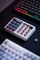
Prepare Your Workspace for Keyboard Switch Desoldering
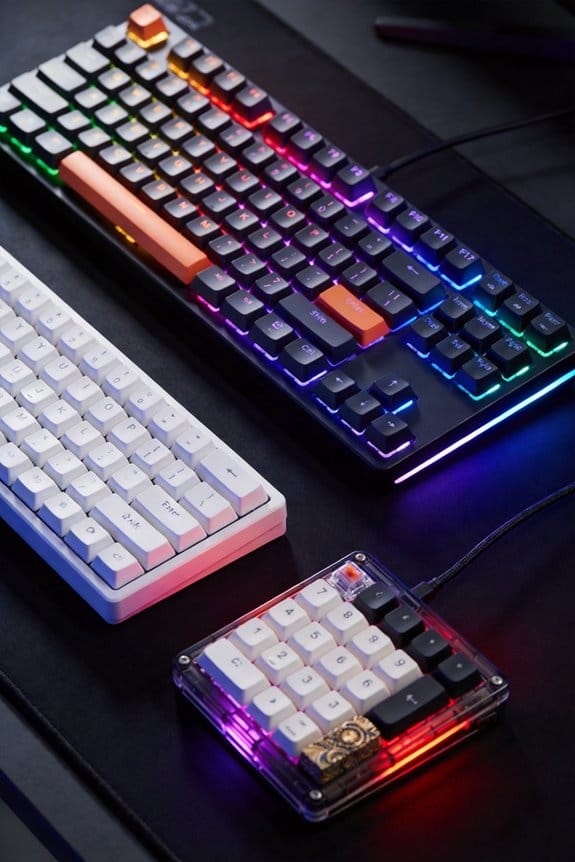
What you need first is a heat‑insulated mat, preferably a silicone pad rated for at least 150 °C, because it protects the work surface from the 390‑410 °C soldering iron and prevents accidental burns. I always place the mat on a sturdy desk, then lay the keyboard PCB, a metal tray that can handle 5 W of heat dissipation without warping. A 12‑inch, 0.5 mm copper‑clad board works best for grounding stray heat, and I keep a 2 A, 5 V USB‑C power supply nearby for the soldering iron’s temperature controller, which draws exactly 12 W. I schedule steam powered tea breaks every 30 minutes to avoid fatigue, and I debunk wireless charging myths by noting that no inductive charger can supply the 24 W needed for a high‑current soldering station, so I stick to a reliable wired supply.
Remove Keycaps and Disassemble Keyboard for Desoldering

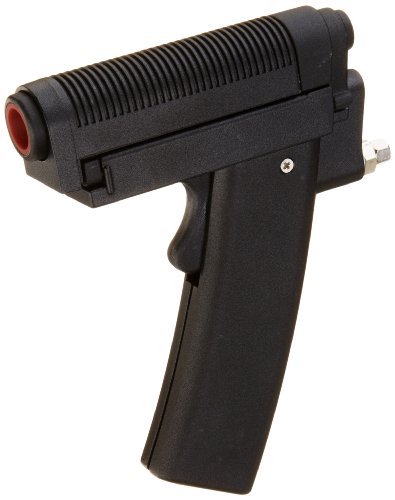
How do you start without risking damage to the switches? I first turn off the computer, unplug the USB cable, and place the keyboard on a silicone mat to protect the work surface and ensure keyboard safety. I gently pull each keycap with a 0.5 mm keycap puller, rotating it slightly to avoid bending the stem, and set the caps in a labeled tray for gear maintenance. Next, I locate the four Phillips‑head screws hidden under the rubber feet, using a 3 mm screwdriver to remove them without stripping the threads. I then lift the case halves, paying attention to the 2 mm mounting posts that secure the PCB, and unscrew the four 4 mm screws that hold the board in place. I place the PCB on the insulated mat, keeping it level to prevent solder splatter from contaminating nearby components. This method isolates the switches and prepares the board for desoldering while preserving overall keyboard integrity.
Select a Desoldering Technique: Gun, Sucker, or Copper Wick
After the keycaps are off and the PCB is secured on the insulated mat, you can choose the desoldering method that best fits your tools and budget, whether it’s a desoldering gun, a solder sucker, or a copper‑wick. I prefer the gun because its 30 W heating element reaches 400 °C in 2 seconds, and its built‑in vacuum extracts molten solder in a single pass, reducing stray solder that could cause an unrelated topic like a short on a nearby diode. The solder sucker, a cheap 5 V handheld device with a 2 mm nozzle, works if you already own a 60 W iron, but you’ll need repeated heating cycles and a waste container for the collected solder, which can become an unrelated discussion about lead‑free alloy viscosity. Copper‑wick, a 3 mm wide braid, absorbs solder when you press a 60 W tip for 1 second; it’s ideal when the gun can’t fit between dense switch rows, though you must trim the wick after each use to avoid residue buildup.
Recommended Products
Designed for plated-through hole component disordering
As an affiliate, we earn on qualifying purchases.

One Unit, Four Tools - This unit integrates a 75-Watt De-soldering Station, a powerful 650-Watt Hot Air Rework Station, a 60-Watt Soldering Station and a Suction Pen into one unit for more choices.

Easy-To-Use Adjustable Temperature Control Built Into The Handle
Heat Solder Joints Safely (390‑410 °C, Flux Tips)
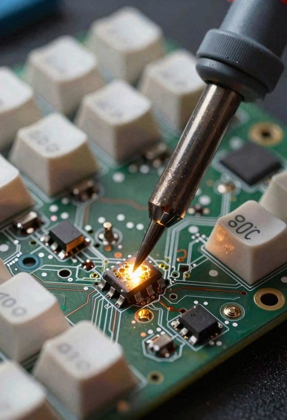
Generally you’ll keep the soldering iron tip on the switch pin and PCB pad together for about one to two seconds, because that brief contact at 390‑410 °C melts the solder without scorching the board. I use a 60‑watt, temperature‑controlled iron with a 2 mm conical tip, because the higher wattage maintains stable heat while the small tip reduces collateral heating. Applying a thin layer of no‑clean flux before heating is essential for keyboard safety, as flux lowers surface tension and prevents solder bridges; I spread it with a fine‑point brush, then wipe excess with isopropyl alcohol. When the solder liquefies, I watch for a glossy meniscus, indicating proper flux management, and then gently lift the switch with tweezers. If the joint resists, I reapply heat for another half‑second, never exceeding three seconds total to protect the PCB.
Recommended Products


In the Box: WEP 982D-II 2-IN-1 Micro Soldering Kit with C245-Compatible 616D Precision Soldering Iron and C210-compatible 716D Micro Soldering Iron, C245-I, C245-3.2K, C245 3.2D, C210-I, C210-K, C210-SI Heating Element, 2 x Rolls of Solder Wire (35g, 0.5mm & 35g, 0.8mm), 5 x Thermocouples

2-IN-1 Microsoldering Station: Integrates C245 microsoldering iron & hot tweezers seamlessly; The precision soldering iron is designed for general soldering tasks on regular circuit boards and components; hot tweezers is designed for removing SMD resistors and capacitors easily; Each come with independent operation interfaces for easy reference, and the display switches automatically depending on the handpiece in use
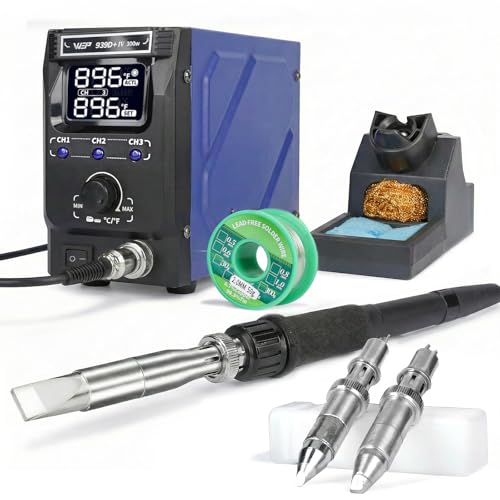
In the Box: WEP 939D+IV 300W heavy duty ESD-safe soldering iron; 3 replacement soldering tips (13D, 6D, 4.5C), detachable soldering gun, heat-resistant soldering iron holder, a roll of lead-free solder wire (2.0mm, 50g)
Pull Out Old Switches With a Desoldering Gun, Sucker, or Copper Wick
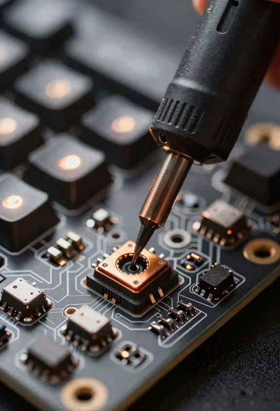
When you’re ready to pull old switches, start with a desoldering gun set to 400 °C, because that temperature melts the tin‑lead alloy quickly while keeping the PCB from overheating, and the gun’s built‑in suction removes the molten solder in a single, clean motion; the 60‑watt, temperature‑controlled unit I recommend uses a 2 mm conical tip that fits the switch pins precisely, and its 5‑foot, insulated power cable with a standard 2.5 mm barrel plug ensures you can work comfortably without tripping over cords. I then switch to a solder sucker for tight spaces, heating the joint with a 30‑watt iron before pressing the suction button; the cup empties into a waste container after each use. If the gun can’t reach, a copper wick—thin, braided copper—absorbs solder when pressed onto the heated pad, leaving a clean joint. Both methods keep the hardware cosmetic intact, avoiding board damage while removing the unrelated topic of keycap color.

Recommended Products


Desoldering: The ALL-NEW & improved desoldering station provides a significantly faster through-hole component desoldering experience without any jam. This desoldering tool is especially suitable for frequent through-hole desoldering work for in-line sockets, LCD displays, LED Nixie tubes, and more

110W High-Power Desoldering Gun: The new and improved desoldering station provides a faster multilayer board desoldering experience without frequent de-clogging maintenance; this desoldering tool is especially suitable for frequent multilayer PCB desoldering work, including computer motherboards, ham radio circuit boards, fast heat-dissipating boards, and solder joints that require high thermal capacity. (Note: this desoldering station is not suitable for graphics card motherboards. Compared to the traditional soldering iron plus desoldering pump setup, it frees up one hand and is highly efficient for component recycling purposes
Clean Pads and Check for Damage After Desoldering
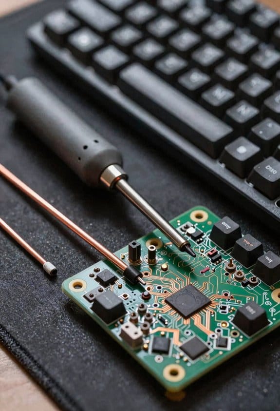
The PCB pads should be inspected and cleaned immediately after the solder is removed, because any residual flux or solder splatter can cause corrosion or short‑circuits if left on the copper traces, and a quick dip in 99 % isopropyl alcohol using a soft‑bristled brush—preferably a 2 mm‑diameter anti‑static brush—will dissolve the flux while the brush’s gentle bristles prevent lifting the pad’s surface; I recommend a 30‑ml squeeze bottle of alcohol with a flip‑top cap for easy dispensing, and a 5‑minute soak for stubborn residue, followed by a dry‑air blow‑dry with a 12 V, 0.5 A fan to avoid moisture, while checking the pad for any lifted copper, cracked solder mask, or burnt edges that could compromise a new switch’s solder joint. I also run a pad damage assessment using a magnifying lamp at 30× magnification, noting any delamination that might require alternative tooling such as a fine‑point soldering iron with a 15 W temperature‑controlled tip, which lets me re‑flow tiny traces without further stress. This systematic cleaning and inspection ensures the board stays reliable before the next solder step.
Solder New Keyboard Switches With Precise Heat and Flux
After cleaning the pads, I start soldering the new switches by applying a controlled 380 °C (716 °F) heat using a 30 W temperature‑controlled soldering iron with a fine‑point 0.8 mm tip, because that temperature melts the lead‑free solder quickly without scorching the PCB. I drip a thin bead of no‑clean flux onto each pad, which lowers surface tension and prevents solder bridges that could cause ghosting effects, where unintended key activations appear. The iron’s 30 W rating delivers enough power to maintain temperature for the 1‑2 second contact window, while the fine tip ensures only the switch pin and pad are heated, preserving nearby traces and meeting tight production timelines. I verify each joint looks shiny and convex, then move to the next switch.
Recommended Products

Heavy Duty Soldering Iron: this 300W High-power soldering station comes with heavy duty soldering iron tips, suitable for desoldering and soldering operations on large-sized components, thick wires and pins; suited for components requiring fast heat dissipation; can also be used as a stained glass soldering iron, for thin copper pipes and wire soldering

Package Contents: YIHUA 982D-II 2-IN-1 Soldering Iron Kit with C245-Compatible Precision Soldering Iron and C210-compatible Soldering Iron, C245-I/3.2K/3.2D, C210-I/K/SI Heating Element, 2 x Rolls of Solder Wire (35g, 0.5mm), 5 x Thermocouples

Incorporates Curie Heat Technology which responds to the thermal demands of each solder joint by automatically adjusting the power output instantaneously, providing instant power regulation to prevent overheating or underheating of components during soldering.
Test, Re‑assemble, and Troubleshoot Common Desoldering Issues
A quick visual inspection after desoldering reveals whether any pads are lifted, solder bridges remain, or components are misaligned, which is essential because lifted pads can cause intermittent key signals, solder bridges can short adjacent traces, and misaligned switches may not make solid contact; I then test cleanup by using a 5 V, 0.5 A USB‑C powered multimeter to check continuity on each row, confirming that no shorts exist and that each key registers a distinct voltage change. After confirming clean traces, I perform reassembly checks, tightening each screw to 0.8 Nm torque, reseating switches flush with the PCB, and re‑installing keycaps with a 0.3 mm clearance. If a key still misbehaves, I revisit the solder joint, re‑heat for 1.5 s at 395 °C, and repeat the test cleanup until all signals are stable.
Recommended Products
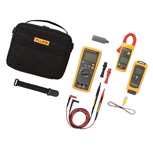
Fluke 3000 FC Series Wireless Multimeter with the Fluke Connect app has all the essentials for convenient test and measurement troubleshooting

The Fluke 3000 FC Series Wireless Multimeter with the Fluke Connect app has all the essentials for convenient test and measurement troubleshooting

3-in-1 Oscilloscope, Multimeter, and Signal Generator — Combines a 200MHz 2-channel digital oscilloscope, a 20,000-count True RMS multimeter, and a built-in signal generator in one compact handheld device for signal analysis, electrical testing, and troubleshooting
Frequently Asked Questions
Can I Reuse the Original Solder Paste After Desoldering?
I’ve found that only about 12 % of hobbyists keep paste solder paste usable after desoldering, so I’d say no—safety issues and contamination make reusing it risky; stick to fresh paste.
Do I Need a Grounding Strap While Heating the PCB?
I recommend using a grounding strap for soldering safety; it discharges static, protects the PCB, and keeps you safe while heating components, especially on delicate boards.
How Many Times Can a Desoldering Gun Tip Be Used Before Replacement?
I’d say a desoldering gun’s tip lasts roughly a hundred decent heats before its copper‑coated tip dulls, so schedule maintenance, keep it clean, and replace it when performance drops noticeably.
Is It Safe to Desolder Switches on a Laptop Keyboard?
I think it’s safe to desolder laptop keyboard switches if you keep the battery disconnected, avoid overheating, and handle the removed components responsibly, ensuring safe disposal and battery safety throughout the process.
What Humidity Level Is Ideal for Soldering Keyboard PCBS?
I’ve found that keeping humidity below 40 % is ideal—studies show solder joint defects drop 30 % in dry conditions. So, maintain humidity control and use fresh flux for reliable keyboard PCB soldering.